Show Control Points and Wireframe, Improved Sketch Tool, Experimental Panel, and More
July 10, 2024
Hello everyone!
Here is a quick summary of what was developed since the last news:
- You can now show the underlying control points of edges, show edges in wireframe mode, and increase/decrease the sampling quality of edges.
- After quite a long research and development effort, sketched strokes now look much better.
- There is now an Experimental panel for advanced options.
- A Width Smoothing option was added to the Sketch tool.
- A combo box user interface component was implemented.
All of these are presented in more detail below.
Show Control Points, Wireframe Mode, Sampling Quality
Let’s start with a description of the following new items in the View menu:
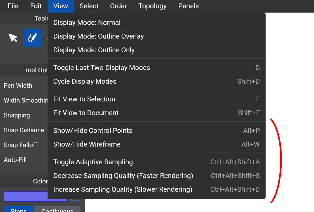
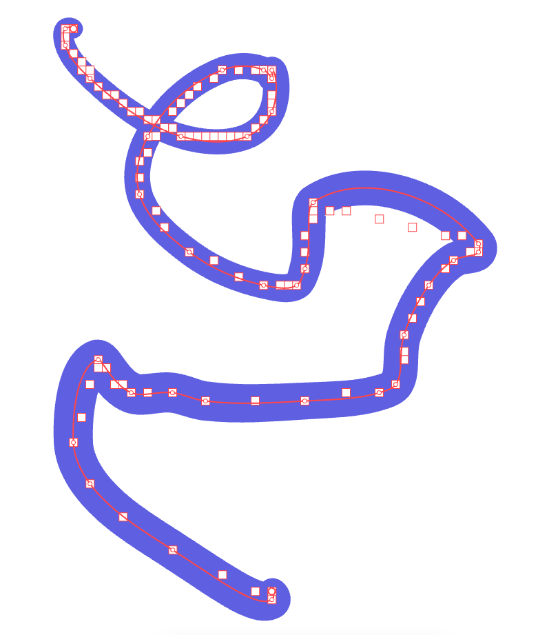
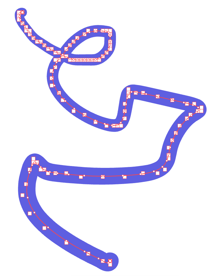
Show/Hide Control Points: This allows you to see the underlying control points of each edge. It is not yet possible to edit them manually (coming soon), but it may help you understand what happens under the hood when you use the Sculpt tool for example.
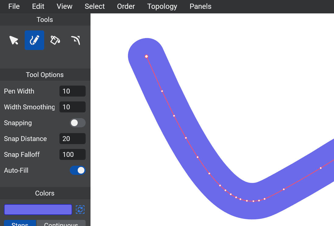
Show/Hide Wireframe: This allows you to see the underlying triangles that are sent to the GPU for rendering.
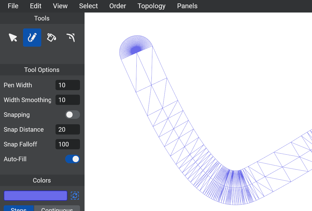
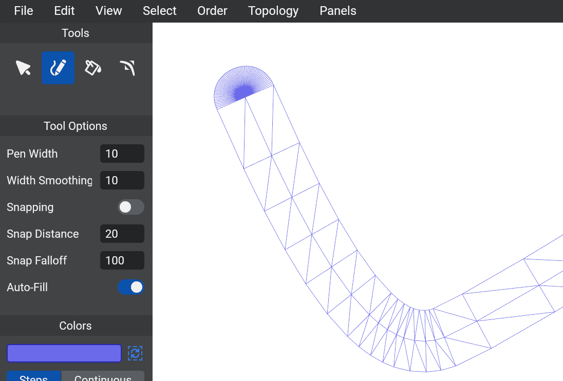
Toggle Adaptive Sampling: This allows you to switch between “Adaptive Sampling” (the default) and “Uniform Sampling”. Typically, it is better to use Adaptive Sampling (image above), which means that the number of triangles used depends on how curved the stroke is. Using Uniform Sampling (image below) means that the number of triangles used between two control points is fixed.
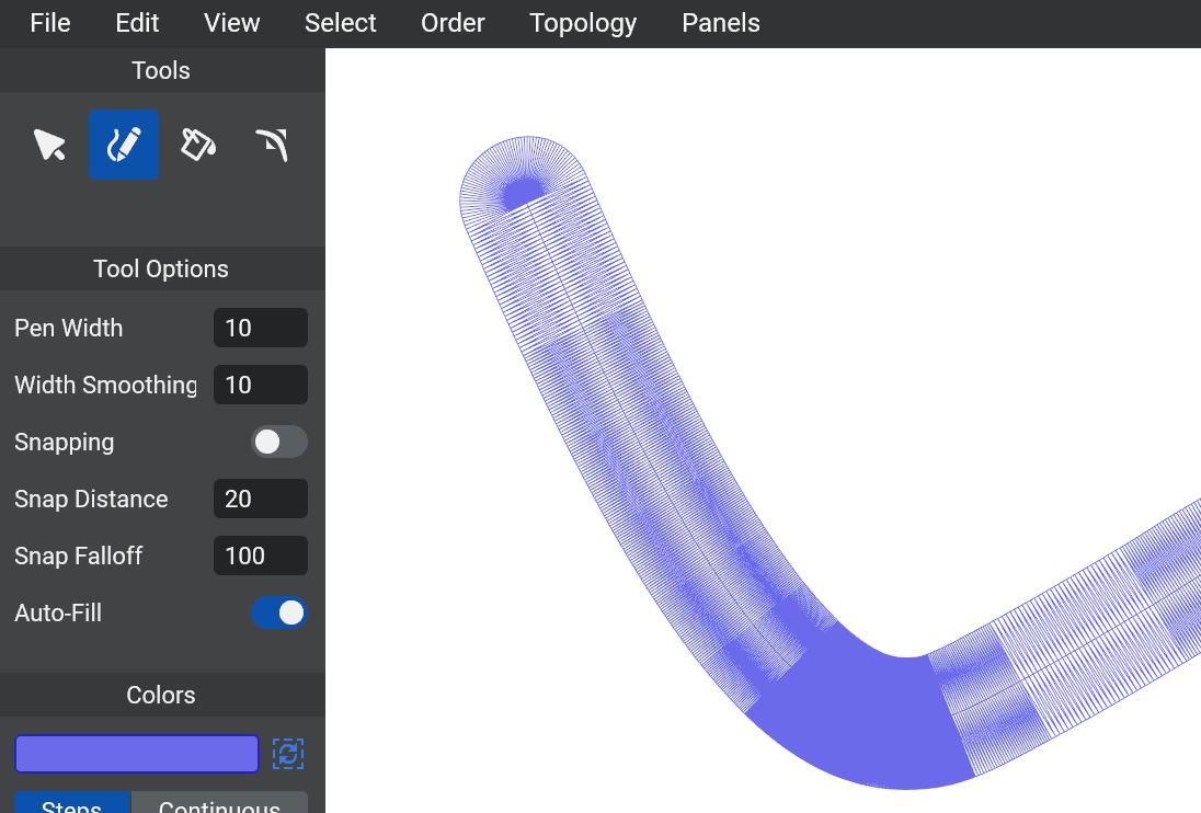
Increase/Decrease Sampling Quality: This works for both Adaptive Sampling and Uniform Sampling. It allows you to increase or decrease the number of triangles used to render the edges. More triangles (image above) means that the curve will look smoother, but it will be slower to render. Fewer triangles (image below) means that it will be faster to render, but you might see undesirable sharp angles between adjacent triangles.
Improved Sketch Tool
I believe that sketching is the most important part of a 2D drawing application, so it is worth spending development time to ensure that VGC Illustration provides the best possible user experience in this area. Sadly, in many vector-based tools, the sketching experience isn’t great:
- In some software, only a rough preview is displayed when sketching, and the final stroke is only computed and rendered when the mouse button is released.
- In some software, the final result can be either too smoothed, or not smoothed enough, or in general quite different from the live preview (when there is one).
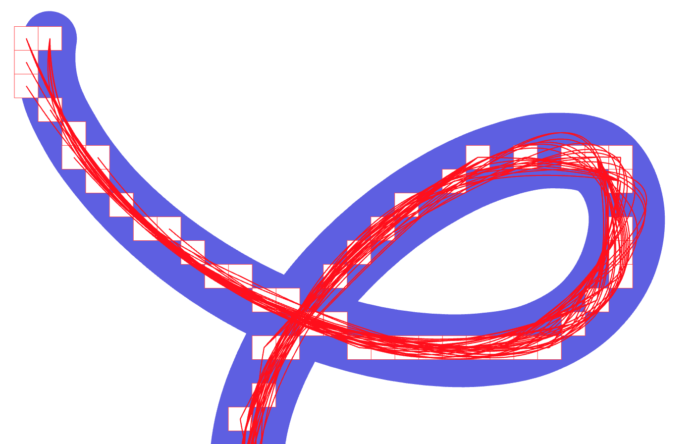
This is because computing beautiful curves out of your mouse/tablet input is actually not an easy mathematical/engineering problem. Why is it hard? One reason is that the input points that the software receives from the operating system (or UI library) are themselves not great: there may not be enough points, and the values may be rounded to the nearest integer pixel.
For example, here is the kind of input data that the application receives from the Qt library when drawing with a Wacom Intuos on macOS (zoomed in around 10x):
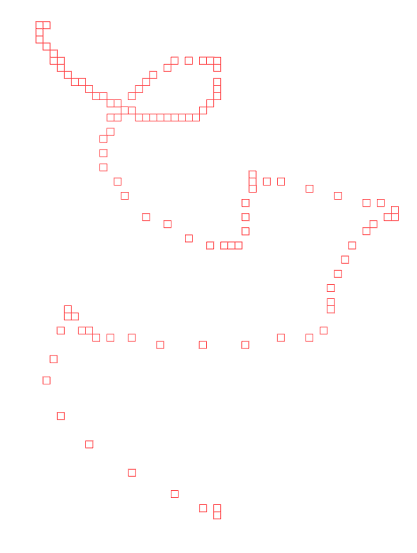
Each little square represents one input point, and the size of each square corresponds to the size of one screen pixel at the time of sketching. The challenge is to turn the above “pixelated” input into one beautiful continuous curve.
Note that drawing with a pen tablet on Windows or Linux typically provides better input (not rounded to integer values), but drawing with a mouse still provides an input similar to the above.
If we simply create a curve interpolating all of these input points, the result is going to be very “wobbly”. Below is the result using Centripetal Catmull-Rom interpolation, but any interpolation method would result in something similar:
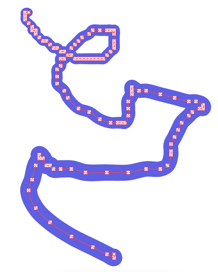
This wobbliness is very undesirable because in addition to being (arguably) ugly, it means a ton of triangles have to be used to render the stroke, slowing down the software (more lag), and also because the user did not even draw a wobbly stroke in the first place! Indeed, the wobbliness is not caused by the user’s hand shaking, but by the hardware/software rounding the values before VGC Illustration receives them. The technical term for this is "quantization", and this means that VGC Illustration needs to somehow dequantize back the data.
In order to solve this problem, one option is to use an algorithm called Douglas-Peucker, whose idea is to only keep a subset of these points. This does result in a smoother curve, but one problem is that interpolating the remaining points does not always stay close to the original points:
Another idea consists in smoothing the input by replacing each input point by a weighted average between the point itself and its neighbors. This is sometimes called Gaussian Smoothing or Weighted Moving Average.
Below is the result using four neighbors (two on each side). It actually works quite well on this example, but it tends to shrink loops and cut corners, especially when drawing fast:
In order to improve this, I developed a new approach which consists in locally computing a lot of tiny overlapping curves (each curve is a Quadratic Best Fit of a subset of the input):
And then blending them in some way to produce the final result:

I will not bore you with more details and comparisons here (this would be the job of a research paper), but typically this new method results in much nicer curves while staying very close to the original input points. Perhaps more importantly, and what makes this method stand out compared to others, is that each new input point tends to not significantly change the previous result (without the new point). This means a more satisfying user experience, with a real-time preview almost identical to the final stroke, and with good consistency and predictability.
Note that VPaint was already using a similar technique, but a simpler version. In VPaint, the local fits were always using a fixed number of input points, while VGC Illustration adaptively decides the most appropriate number of points based on how good the fits are. In particular, it uses fewer points around corners, so it does not cut corners as much as VPaint does. Also, the local fits themselves are computed using more robust techniques, resulting in a curve closer to the original input, and without some of the undesirable flickering that VPaint sometimes have.
I hope you will enjoy this new sketching experience! If you have access to the alpha versions, any feedback on Discord is appreciated.
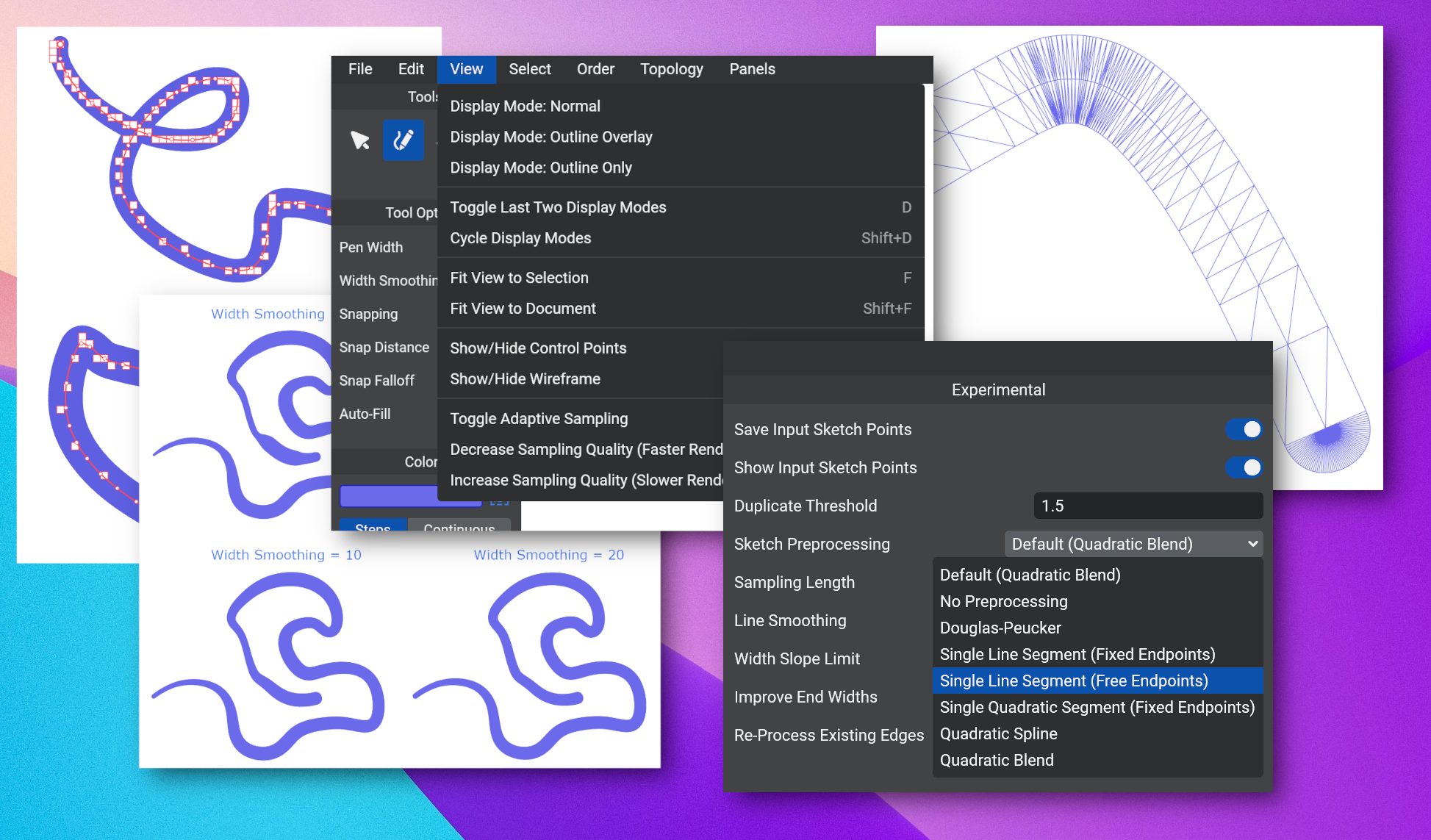
Experimental Panel
There is now an Experimental panel for advanced options that might be useful, but are either temporary or not polished enough to be part of the main interface.
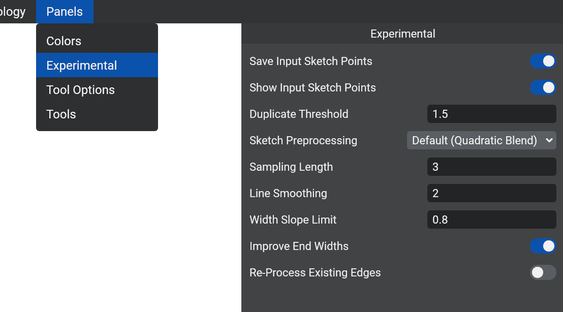
For now, it mostly contains controls that were useful for developing and testing the new sketching algorithms.
Save Input Sketch Point: Specifies whether the original input points from the mouse/tablet should be saved for later use. This must be enabled before sketching an edge for “Show Input Sketch Points” and “Re-Process Existing Edges” to work for this edge.
Show Input Sketch Points: Specifies whether the original input points for the mouse/tablet should be visible. They are shown as little red squares that have the same size as one pixel when originally drawn (see images in the previous section).
Duplicate Threshold: Specifies the distance, in screen pixels, under which two input sketch points are considered “duplicates”. When points are duplicates, only the first is taken into account and the others are ignored for further processing. This step is applied first before even “preprocessing”. Using a value of 1.5 tends to improve the results, especially with “pixelated” input data. You can experiment changing this to a smaller value (or even 0) if you are using a high-precision tablet on Windows or Linux, which may give you a bit more details out of your strokes, which is useful for example when hand-writing text.
Sketch Preprocessing: Specifies which preprocessing algorithm is used to convert the input points to a list of control points. It is recommended to keep the default (Quadratic Blend), which is the algorithm explained in the previous section and usually gives the best result. You can use “Single Line Segment” if you want to draw straight lines :) Of course, a more intuitive way to draw straight lines will be implemented later, for example holding Shift in the Sketch tool and/or via a separate Line tool.
Sampling Length: Specifies how many control points should be in the output, expressed as a distance in pixels between consecutive control points. Use a smaller value if you want more control points, and a larger value if you want fewer control points. Currently, this is only available if the preprocessing is Quadratic Blend.
Line Smoothing: This is an extra smoothing step that is applied after preprocessing. For now, it is based on Gaussian Smoothing (see section above), and only works well for small values. If you want smoother curves you can increase the value, but for now it does not give great results at stroke ends for large values. The algorithm will probably be improved later, in which case this would be moved from the Experimental Panel to the Sketch tool options.
Width Slope Limit: This ensures that the width of strokes does not increase (or decrease) more than the distance between control points, multiplied by this parameter. This prevents some undesirable artifacts that occur when the width changes too fast.
Improve End Widths: Using some tablets, the first and last control points sometimes have widths that suddenly drop to very small values (or zero). This often does not look very good, and enabling this option corrects these widths to more reasonable non-zero values. Feel free to disable if you actually prefer to keep the end widths as is.
Re-Process Existing Edges: If this option is enabled, then changing any of the above settings (except Save/Show Input Points) would automatically reprocess all edges that have saved input points, by applying to them the new settings. This can be very useful for comparing different settings: enable Save Input Points, draw a few strokes, then change the settings and see in real time how it affects the strokes. Warning: if there are many strokes, this can be quite slow, so it is generally advised to keep it disabled, and only enable it for testing with just a few strokes on your document.
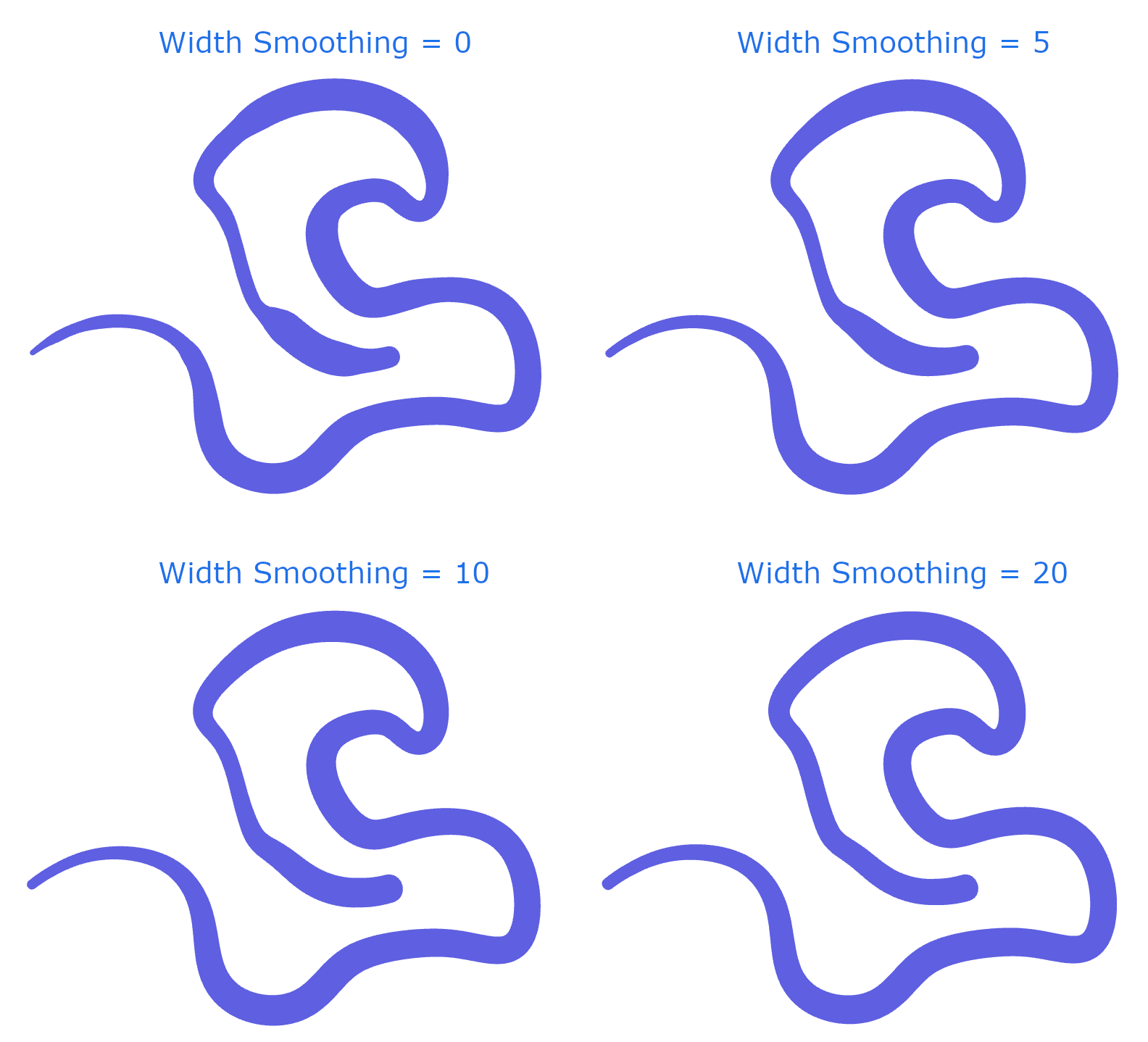
Width Smoothing
This is a parameter that made it directly to the Sketch tool options panel, without going through the Experimental panel!
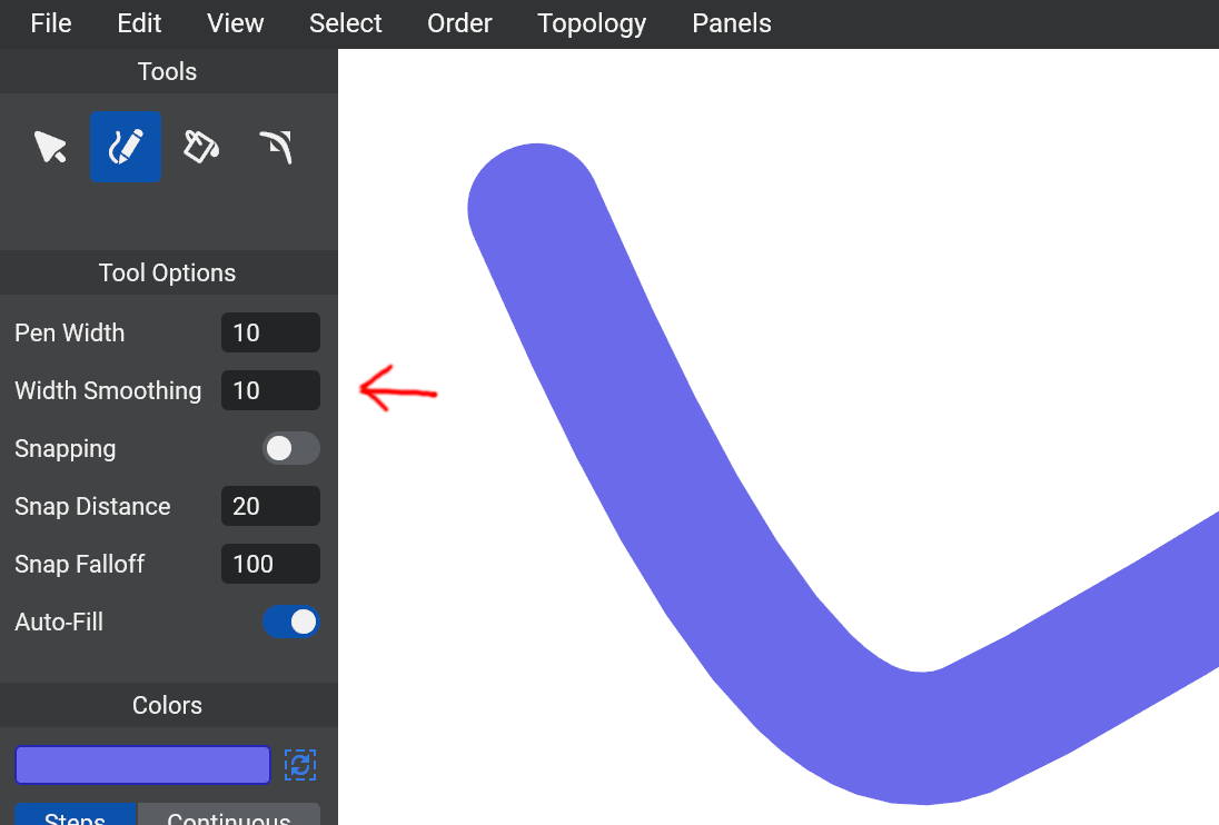
It specifies how much smoothing you want to be applied to the variable width of the curve. The number corresponds to how many neighbor control points (on each side) are used for the smoothing operation.
If Re-Process Existing Edges is enabled in the Experimental Panel, and if Save Input Sketch Points was enabled when sketching the edge, then modifying the Width Smoothing value will retro-actively modify the edge, but any sculpting that was done between drawing the edge and modifying the Width Smoothing value will be lost (although you can still undo it).
The above also applies to all sketch settings in the Experimental panel.
Combo Box
This is the classic user interface component that allows users to select one option among multiple options via a dropdown menu.
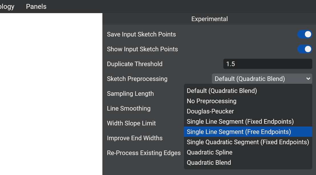
For now, it is only used in the Experimental panel for the Sketch Preprocessing setting, but it will probably be used in a lot more places in the future, so it was important to implement it.
What’s Next?
The next big thing to implement is the “Auto-Cut” mode of the Sketch Tool, which can be used to automatically create a vertex when edges intersect, and automatically split a face into two faces when sketching an edge that cuts through the face.
Stay tuned!
Stay tuned
Found this news interesting? We can send the next ones straight to your inbox (around twice a month). Or we can simply let you know when VGC 1.0 is released. No spam guaranteed. You can unsubscribe at any time.